Archives

All posts by Steven Keyes

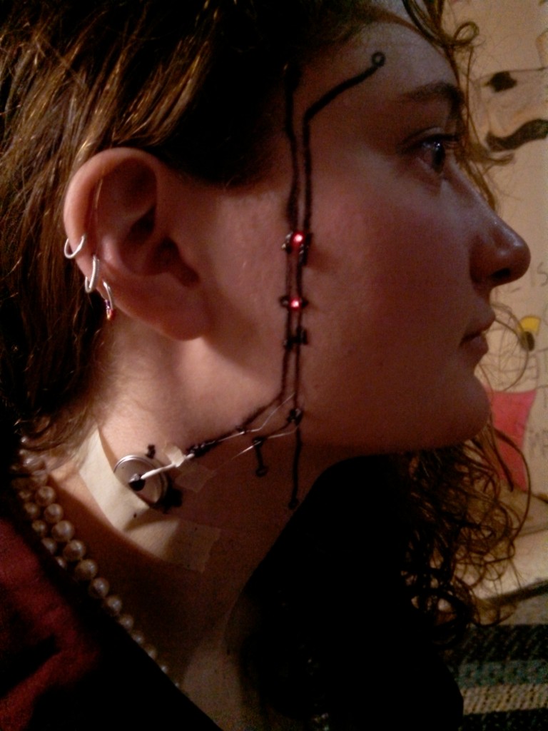
Ever wanted to be a robot? Become 0.02% more cyborg with Electronics Facepainting!

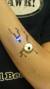
Becca G. demonstrates being a cyborg.

Becca G. demonstrates being a cyborg.

I initially had this idea when I heard about a new printer that could print on a variety of materials (c/o Hack a Day). The printer works by printing traces with silver nitrate solution, which precipitates onto the substrate when a second chemical, ascorbic acid, is added. Right off hand, these chemicals struck me as not particularly bad for humans beyond their staining and being mild skin irritants. This gave me the idea to apply them to people. Their risks were minor for the sake of art.

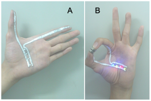
Unfortunately, silver nitrate solution is rather expensive; taking this into account, I searched for an alternative chemical for skin-based circuit traces. The next idea I found was a gallium-based ink, tested in a 2013 research paper I found online by Yu et al. at Tsinghua University. The LEDs on a hand in one of their pictures inspired me, but again gallium was too expensive for my purposes.

A researcher demonstrates  a circuit made with gallium paint, c/o Yu et al.

A researcher demonstrates a circuit made with gallium paint, c/o Yu et al.

There are a variety of sources online for how to mix your own conductive paint, conductive rubber, or conductive glue. Most involving mixing the non-conductive version of the substance with graphite powder and produce relatively high resistance products.

However, I settled on Bare Conductive, which makes a non-toxic, reasonably priced conductive ink. Some of their initial videos suggest their product is skin-safe and intended for skin, but they appear to have gone back on this since the Bare Conductive MSDS now recommends against skin contact and any mention of skin is absent from their website. The MSDS warns that it “may cause skin sensitization” due to an allergy to the Diazolidinyl urea in the paint. Maybe they’re also worried about people attaching volts to their skin and zapping themselves.

Anyway, I went with their earlier advice since I had already decided I was fine dealing with mild dermatitis. I ordered a batch for the East Campus Bad Ideas Festival, though I ended up not using it until later. When it arrived, my friend Becca G. and I played around with various techniques before demonstrating it at a party and later MIT Campus Preview Weekend.
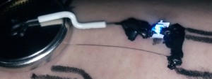
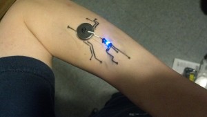
This is the first circuit I painted on my arm. I added details with eyeliner.

This is the first circuit I painted on my arm. I added details with eyeliner.

I used Bare Conductive for connections and strands of wire for long traces.

I used Bare Conductive for connections and strands of wire for long traces.

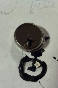
This close up shows the strand of wire as well as the slip of paper I inserted under the LED to make up for my sloppy connection work.

This close up shows the strand of wire as well as the slip of paper I inserted under the LED to make up for my sloppy connection work.

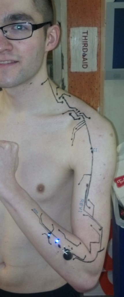
We decorated and annotated the circuits with black, metallic, and neon eye liner pencils. Here are some pics of Becca and me before a party.

RoboBECCA 9000

RoboBECCA 9000

My other arm is robotic.

My other arm is robotic.

One thing we noticed immediately was that the conductive ink, while conductive, still had quite a bit of resistance. It turns out the ink is OK for electrical connections and great for making resistors in the 100Ω to 10kΩ range, but pretty bad for making regular traces longer than an inch. As a compromise, I pulled some single strands out of some stranded wire and used these for long traces, securing it with the paint, which I treated like glue or solder.

Mostly, we just painted LED circuits, but I tried a few others. Here’s an oscillator on some paper that didn’t end up working, and I never got a change to debug it further before I cleaned up. That said, I’ve constructed this circuit on a breadboard and artificially added a couple hundred ohms of resistance at every electrical connection to simulate the resistance of the paint at joints, and it worked great, so I suspect this circuit could be successful with some tweaking.

Works on paper (top right corner), but doesn't work on this paper

Works on paper (top right corner), but doesn’t work on this paper

One problem I had was the fragility of the circuits–it was important to avoid accidentally brushing your skin against any rough surfaces. In the future, I’d like to try using clear liquid latex to secure some of these circuits.

If there’s interest in this, I can post some step-by-steps on how to make your own Electronics Facepainting.
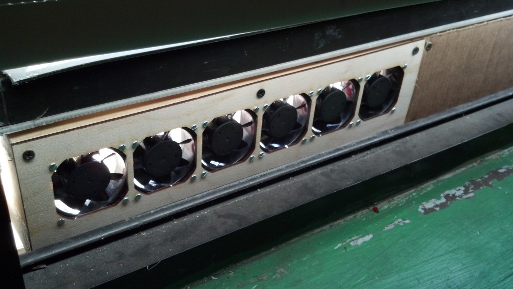
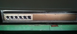
A few days ago I made a low-profile fan for my window out of computer fans. I wanted to mount the fans in a laser-cut frame, so I started by taking measurements and drafting the design in SolidWorks.

This row of fans takes up only a few vertical inches of window real estate.

This row of fans takes up only a few vertical inches of window real estate.

Often, when I make a design in SolidWorks, I include a file for storing global variables for my project. I liken this to defining global variables or constants at the beginning of a software project. I use this technique frequently to great utility in SolidWorks, but I don’t see very many colleagues use it, so let me elaborate on it.

First, I make a text file called “dimensions.txt” or similar, and, in it, I list all the global variables I’d like to use in my project, like the example below. These include values that I’d like to be the same across parts files. I also include values that I think will have to be changed by the end of the project.

For example, for this project, I thought I might change what computer fan I used and how many I used, so I included mounting dimensions for the fan as well as the quantity of fans.

However, I knew the width of the window wouldn’t change, and was only used in one or two parts, so I didn’t include that constant in my list of project-wide constants.

"dimensions.txt"

1 "depth" = 0.98
2 "side" = 2.36
3 "hole spacing" = 1.97 'horizontal or vertical distance between two holes
4 "fan diameter" = 2.52
5 "fan count" = 6
6

There are some tricks to this text file–for SolidWorks to understand it, all variables must be enclosed in quotes ( ” ” ), comments must be preceded by a single quote ( ‘ ), and the file must end with a newline. Note that in the box above, the numbers on the left mark the lines but are not in the actual text file.

I save dimensions.txt in the root directory of my SolidWorks project. Then, whenever I make a new part, I first use the Equations dialogue in SolidWorks to import this file into the list of parameters for that part; the screenshot below shows the Equations dialogue after importing dimensions.txt. For a parametric modeling software, I think SW sure has this parameter dialogue tucked away, so I have it hotkeyed to Q, the same as the default in Autodesk Inventor, if I recall correctly.

I added a few values to this part that were derived from the globals in dimensions.txt, but that weren't necessary to be known by every part in the assembly.

In addition to the globals imported from dimensions.txt, I added a few values specific to this part, the front panel. These values in particular were derived from the globals in dimensions.txt, but they weren’t necessary to be known by every part in the assembly.

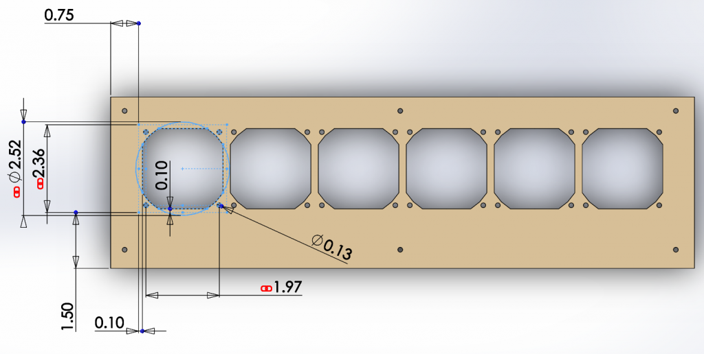
Then, whenever I dimension a sketch or feature in the part, I link those values to the global variables imported in dimensions.txt, as shown below.

I linked the values of the dimensions here to my global variables, as indicated by the red chainlink symbol.

I linked the values of the dimensions here to my global variables, as indicated by the red chainlink symbol.

This allows me to change parameters after I’ve finished the basic CAD. Whenever the part or assembly is rebuilt, SolidWorks automatically refreshes the values in dimensions.txt. Consequently, I can change one value with my text editor, rebuild the top-level assembly in SolidWorks (ctrl+b), and all files update their parameters from dimensions.txt.

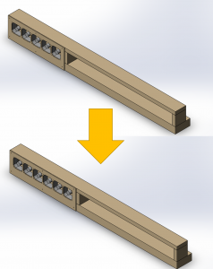
This actually ended up being relevant for this project because I found an extra fan of the same size as my earlier ones, and I wanted to add it to the array. Due to this technique, this change required an order of magnitude fewer operations–my panel and assembly were updated immediately and automatically, as demonstrated below.

Changing from five fans to six required about two clicks instead of a dozen.

Changing from five fans to six required about two clicks instead of a dozen.

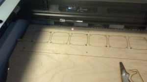
Anyway, after I made this design, I laser cut the front panel.

I'm a huge fan of how fast laser cutters are.

I’m a huge fan of how fast laser cutters are.

Then, I screwed it all together and ran it off of a 5V couple-Amp power supply.

I covered the rest of the fan box with a sheet of cardboard.

I covered the rest of the fan box with a sheet of cardboard.

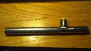
My friend Kamal needed some practice welding before he started on his sweet bike frame, so he asked around if anyone needed stuff welded. Rather than weld some modern art together, we came up with something entertaining, yet still trashy. I give you: the industrial-grade steel Kazoo:

This beauty will survive even a frustrated listener ripping it from a 9-year-old's mouth and kicking it out a window.

This beauty will survive even a frustrated listener snatching it out of a 9-year-old’s mouth and kicking it out a window.

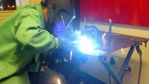
First, we cut appropriate holes in some steel pipe. Then, we welded the pieces together.

Kamal welds some bike-frame-sized scraps of pipe together.

Kamal welds some bike-frame-sized scraps of pipe together.

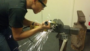
Since he wanted to get a solid seal around the weld where the two pieces met to form a T but it was some of his first work, Kamal ended up with some excess weld, so he ground it off.

Kamal smooths off the weld of the kazoo.

Kamal smooths off the weld of the kazoo.

After we deburred the pipe, I used a small piece of PVC pipe to stretch and hold some plastic from a grocery bag, plugging the little end of the kazoo. Here’s how it sounds.

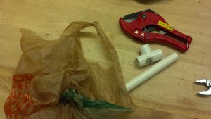
That said, it’s even easier to make a kazoo with some PVC tubing. All you need is a T joint, about a foot of PVC, a PVC cutter, and a plastic grocery bag. I made a couple of these in high school and found 1/2″ ID makes the best sound.

This is all you need for the world's most annoying instrument.

This is all you need for the world’s most annoying instrument.

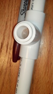
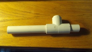
Then, you cut the PVC to appropriate length and cut out a square of grocery bag, plugging it into the middle hole of the T joint. These are also fun to decorate.

Play around with the tightness of the grocery bag, but try not to rip it.

Play around with the tightness of the grocery bag, but try not to rip it.

This one's a little less industrial but it still quite loud.

This one’s a little less industrial but it still quite loud.


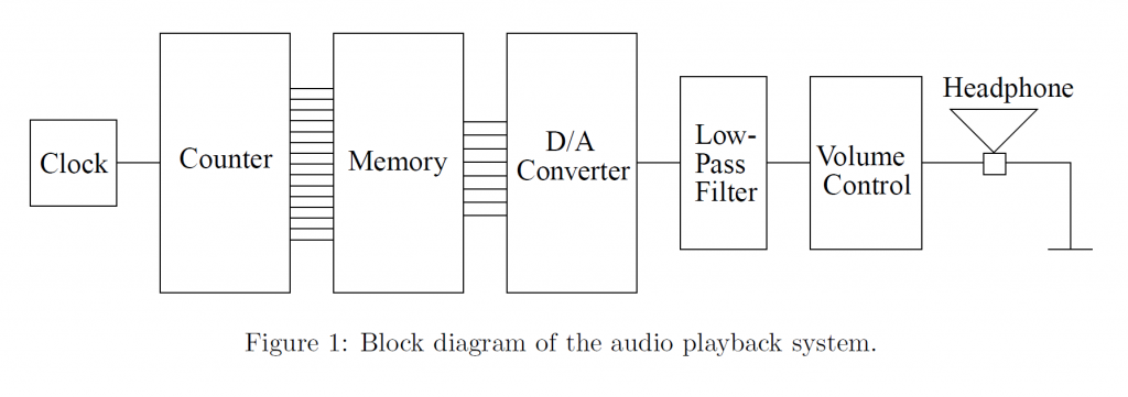
This isn’t a project that I came up with, but it’s the final lab project for MIT’s introduction to circuits class (6.002), and I thought it was a neat project that brought all the phenomena we studied over the semester as well as encouraging modular circuit design, so I wanted to share it with you. The project was to build a music playing system, as shown in the following block diagram. A memory unit was given to us, but we built a clock, a DAC, an active low pass filter, and a small amplifier.

This block diagram of the music player was taken from the 6.002 OCW website.

This block diagram of the music player was taken from the 6.002 OCW website.

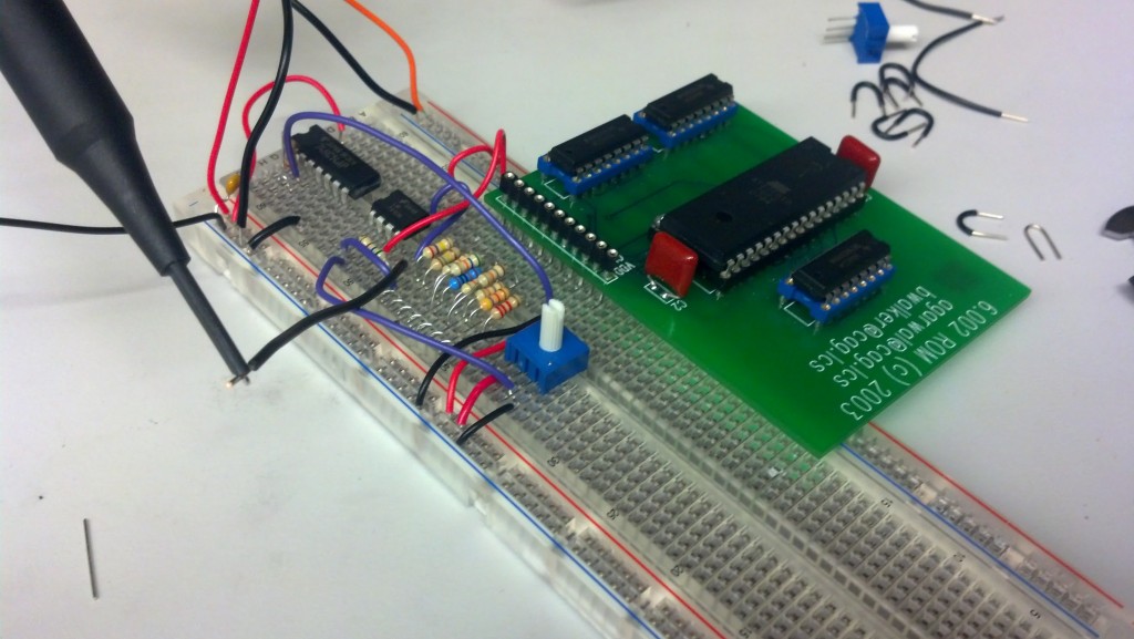
The clock was simply a square wave generator made with a Schmitt trigger. The DAC required a set of resistors with certain relative values, so I made a python script to select a set of resistors. The script looked at the set of all standard resistor values in the lab to which I had access as well as the combinations of those values in series and parallel, and it sorted those by total error. From the results, I selected a set that had mostly single resistors rather than combinations, for ease of assembly. You can see the pile in the middle of the breadboard.

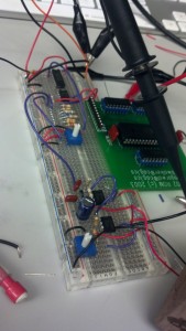
I built this part first. It contains the timer, counter, memory, and DAC.

I built this part first. It contains the timer, counter, memory, and DAC.

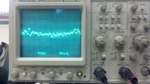
I tested each module after I built it.

The signal from the memory had high frequency noise due to being discretized.

The signal from the memory had high frequency noise due to being discretized.

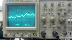
The low pass filter smoothed the noise out.

The low pass filter smoothed the noise out.

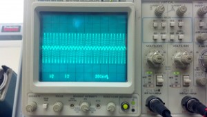
Here, the amplifier scales a sine wave.

Here, the amplifier scales a sine wave.

I added a low pass filter and amplifier at the bottom of the breadboard..

I added a low pass filter and amplifier at the bottom of the breadboard.

Here’s a thing I built for EC Rush 2013. It’s a swingset, but instead of seats, it contains a suspended sofa.

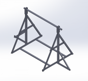
It’s not that complicated, so I won’t say much. Here’s a frame.

I drafted the frame in Solidworks and submitted a bill of materials and proposal to the EC Rush Chairs to get lumber.

I drafted the frame in Solidworks and submitted a bill of materials and proposal to the EC Rush Chairs to get lumber.

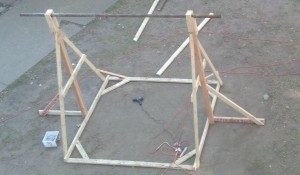
Here’s what it looked like when we built the frame.

This photo was taken from the top of the fort.

This photo was taken from the top of the fort.

Here’s the finished swing.

Cheers.

Cheers.

For the past 7 weeks, I’ve been in China and Taiwan teaching Engineering and American Culture classes for summer camp -style programs at different universities through the program MIT-CETI. It’s been a blast; I’ve met lots of cool people in my travels, and I’m going to miss China and Taiwan a lot.

The first city I visited was Kunming, Yunnan. One of my favorite things about Kunming was the colorful lighting that illuminated the city at night. I’m not just talking about bars and shops. Even office buildings and residential buildings were covered in LED lights, and not just simple lights, but gaudy color-changing, flashing, pattern-changing ones. I thought it made Kunming very pretty, and I wish we had this in Boston. I guess we’ll just have to settle for the Pru.

Anyway, it was so pretty that I made a video. Sorry for the shitty quality; I don’t know how to edit videos, and it was all taken on a cell camera. Still, enjoy!

Last semester, I took a class called 2.007, Design and Manufacturing I, which is a project-based class offered by the mechanical engineering department at MIT (course catalog description). Normally, 2.007 students design and build robots for a competition at the end of the class, but this year 2.007 had two special sections: one for building underwater systems and one for building electric vehicles (EVs). I enrolled in the EV section, and over the course of the semester, my teammate Eric and I built an electric go kart, which we named RoachKart. At the end of the semester, we had a series of races. There’s a lot to say about the kart, but for now I’ll just outline our build process.

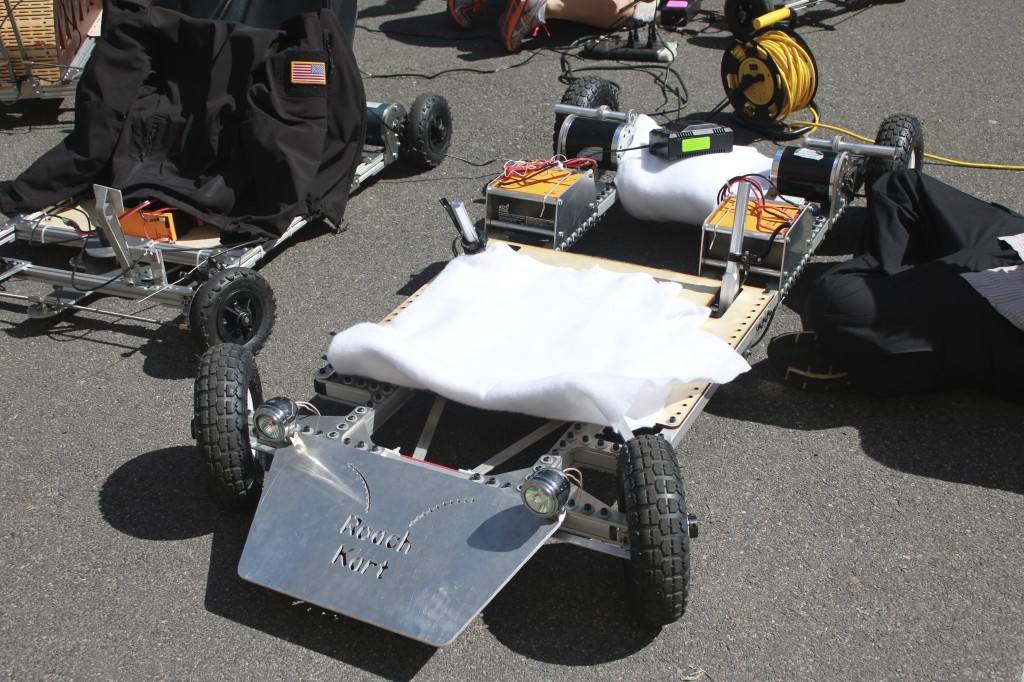
Karts charge prior to the race. Photo by Kirsten L

Karts charge prior to the race. Photo by Kirsten L

Our section was taught by EV extraordinaire Charles G, whose relevant blog is here, and who gave presentations on various aspects of vehicle design throughout the semester. At the beginning of the class, he gave constraints for our go karts–20 mph max speed, braking and steering systems, a $500 budget, and more. With this in mind, we set out designing a kart that would satisfy these criteria as well as being fun to drive.

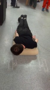
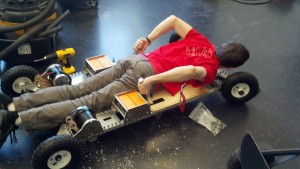
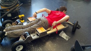
Below, we experimented with various rider positions before settling on a superman-style kart. The rider rests on his stomach with his head facing forward and hands by his sides.

Eric rests on a couch cushion and moves his hands and feet to find comfortable positions for controls.

Eric rests on a couch cushion and moves his hands and feet to find comfortable positions for controls.

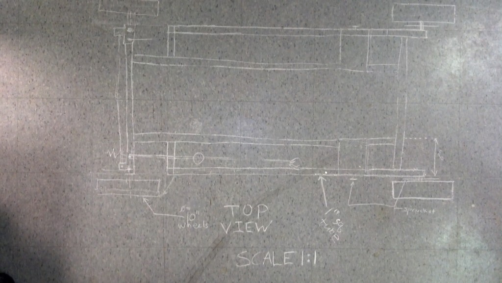
We outlined our design for the kart by drawing on the floor with chalk. Each tile is 1 foot on an edge.

We outlined our design for the kart by drawing on the floor with chalk. Each tile is 1 foot on an edge.

Next, we started designing the go kart in SolidWorks. To collaborate, we set up an SVN repo on which we shared SolidWorks models, pictures, and parts orders. Once we received our first order of parts, we started building the frame. One way we stayed in budget was to use hand-truck wheels from Harbor Freight, which are significantly cheaper than wheels sold on hobby EV sites.

alternatively called ExcessiveScrewHoleKart

alternatively called ExcessiveScrewHoleKart

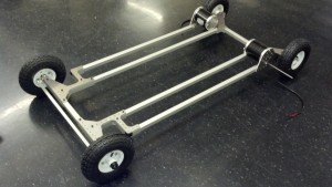
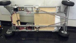
We found a cheap supplier of square aluminum extrusion for the frame and joined the pieces with waterjetted aluminum plates.

We found a cheap supplier of square aluminum extrusion for the frame and joined the pieces with waterjetted aluminum plates.

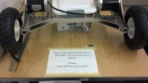
A sign warns students against crowding our table with personal belongings.

A sign warns fellow students against crowding the workspace with personal belongings.

After the frame, we designed more complicated parts like the brakes and steering. Here are prototype versions of them.

Here are prototype versions of steering and brakes.

Here are prototype versions of steering and brakes.

Finally, we finished the steering and started on other mounting hardware, such as battery mounts, the motor controller, and switches.


Eric demonstrates using the levers to turn.

2013-04-10_15-55-17_5042013-04-10_15-55-19_947 Eric demonstrates using the levers to turn.

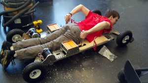
At the end of the build, we wired up the electrical system and installed brakes.

RoachKart is turned on its side to allow access for wiring.

RoachKart is turned on its side to allow access for wiring.

We also added a shoulder rest, white padding for the deck, and a helmet for the rider, all while updating our CAD model to plan what features still needed to be installed.

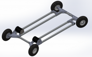
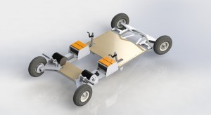
Final CAD rendering shows all major features of the kart except the front cowplow and headlights, which we added on a whim afterward.

130729-kart2 Final CAD rendering shows all major features of the kart except the front cowplow and headlights, which we added on a whim afterward.

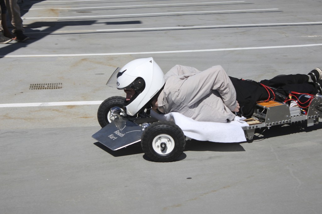
Then, we took it for a test ride. Here’s a video of one of the first times we took RoachKart out. Eric and our TA Banks ride it. You can see here why we named it RoachKart–it’s flat and fast. I like how it has low enough clearance to skit underneath a nearby porch. Without a helmet, RoachKart riders can clear 14″ clearances.

Also, driving so low to the ground is really exhilarating.
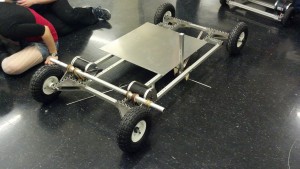
In the end, our kart performed well, scoring both a low time in the final drag race and a low score in the parking garage hill climb, which measured a composite of speed and vehicle efficiency. At our best, our kart went 50 meters in 7.00 seconds starting from standstill.

The kart climbs to the top of a parking garage and races across the finish line. Photo by Kirsten L

The kart climbs to the top of a parking garage and races across the finish line. Photo by Kirsten L

As far as improvements, the biggest thing we would improve if we had time would be the brakes. We implemented scrub-style brakes with a piece of aluminum pressing against the tires, but we suspect disc-style or drum-style brakes would be more effective. In addition, the steering linkages, which were made from 1″x1/8″ aluminum extrusion, could also be improved to bend less in compression. However, for the amount of time we drove the kart, we found that the slop that this contributed to the steering was negligible.

Anyway, there’s lots of go karts that got built, but we think our kart is the most fun to ride.

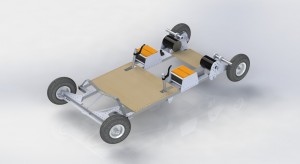
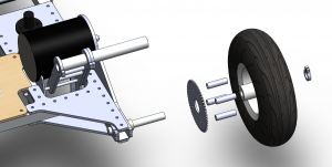
Edit: Someone asked about the rear assembly, so here’s an exploded view!

Shown here is the rear assembly including the motor, motor mount, rear axle, a clamp on the frame that fixes the rear axle, and the wheel sprocket assembly. The wheel sprocket assembly is exploded.

For the rear drive, we waterjetted some large sprockets from aluminum and slightly beveled the edges with a sander. Then, we and then bolted them to the side of the wheels we bought from Harbor Freight, standing them off with spacers. The wheels already had bearings in them, so we simply clamped down the rear axles and slid them on. We also added a clamping collar on the outside of each rear axle to keep the wheel assemblies from sliding off. The sprockets on the motors were also waterjetted, and we screwed them into clamping collars and clamped them onto the motor shafts. We then attached chain (not shown) around the sprockets.

I made a torch! It’s got a decorative twist, which I saw on torches like those sold here.

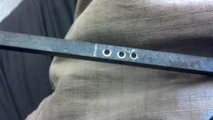
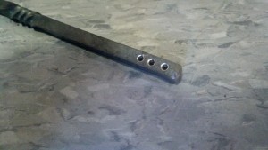
First, I drilled 3 holes in some 1/4″ iron stock. Their purpose comes later.

. . .

. . .

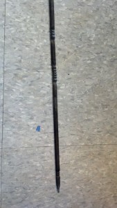
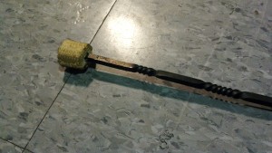
Then, I heated the iron in a forge, tapered the end, and added 3 twists. I learned how to do this in MIT’s blacksmithing seminar. After this, I cut the stock to about 15″, ending at the series of holes.

Adding twists requires heating a short section of the iron and possibly quenching the adjacent areas with water to limit the length of the twist.

Adding twists requires heating a short section of the iron and possibly quenching the adjacent areas with water to limit the length of the twist.

I cut off the extra stock with a cutoff wheel.

I cut off the extra stock with a cutoff wheel.

Next, I added about 9 inches of 1 inch kevlar wick to the end. I used a needle to sew a few meters of kevlar thread through the wick and through the holes to secure the head.

I used a straight needle to sew through the wick and the holes at the beginning. Then, I used a curved needle to sew through the wick.
I used a straight needle to sew through the wick and the holes at the beginning. Then, I used a curved needle to sew through the wick.
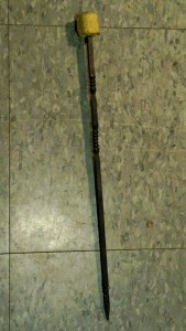
Here's the final product!

Here’s the final product!