Here’s another thing I made using a laser cutter!

Poi Holder

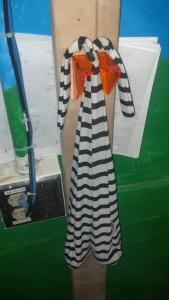
I cut a sock poi holder out of acrylic. It’s a slot with a curved, tapered opening, so it’s easy for poi to slide in to hang and slide out. First, I made a holder out of cardboard, but then I cut some out of acrylic, which resulted in a slot that is a much smoother and less likely to catch.

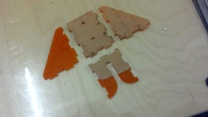
Here are the acrylic pieces. I set the design a few thou large to account for the laser kerf as noted in Charles’s guide.

Here are the pieces prior to assembly.

Here are the pieces prior to assembly.

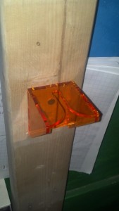
The holes in the back are for screwing mounting the holder.

The holes in the back are for screwing mounting the holder.

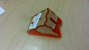
Then, I assembled them and fused them with cyanoacrylate glue.

Wood screws secure this piece against a 2x4.

Wood screws secure this piece against a 2×4.

The color orange is great.

The color is great.

Other Stuff

I also prototyped a mount for an optical quadrature encoder and a mount for a robotic radiator dial controller, but I’ll post about those later.

Laser cutters are really sweet! You just put your material in, and then you wait a few seconds, and you’ve machined this really complicated part. Here’s some stuff I made using a laser cutter over the past year.

Stencil for Bleaching a Shirt

My friend Kirsten L. gave me this idea and helped me make stencils for making bleached T-shirts. Here from Make and here from Stencilry are instructions for making T-shirts with cool graphic effects using bleach and a stencil. However, instead of making a stencil by hand, I used a laser cutter, which was really easy. I didn’t use very complex designs, but a laser cutter would be way preferable compared to hand cutting for very intricate stencils.

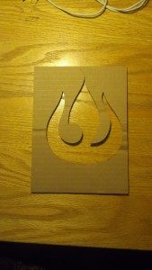
This stencil was cut from cardboard using a laser cutter.

This stencil was cut from cardboard using a laser cutter.

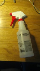
I mixed and sprayed bleach using a spray bottle.

I mixed and sprayed bleach using a spray bottle.

Here’s one with a fire nation symbol. whooo fire.

Here's my shirt!

Here’s my shirt!

I also made another shirt. In my next post I’ll tell you about something else I made with a laser cutter.

This IAP, I worked with a team of 5 undergrads to build an awesome robot that competed autonomously in a ball-collecting game at the end of January.

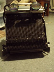
When we started designing our robot and strategy, we focused on simplicity and high ball capacity. To this end, our robot consists primarily of a wide tread belt. This single mechanism pulls in balls, drives them to the top of the robot, and deposits them to a hopper before a gate opens to unload them. We also favored the wide channel of this design over designs that moved balls through a single-file bottleneck. We named our final product EARL, the “Electronic Assistant Research Labrador”.

This rendering made by team member Fred M. is taken from our team journal.

This rendering made by team member Fred M. is taken from our team journal. The black tread is omitted in this rendering, so the wide ball channel is visible below the rollers.

For the code, we used python to implement a state machine that encoded various behaviors. For example, EARL used IR sensors mounted to either side of the conveyor belt to perform wall following to move around the field. Meanwhile, EARL used the camera above the belt to search for red or green balls. For the vision, we used the opencv library.

Beyond the idea of a big tread, we also implemented some cool lower-level things. I worked a lot on programming and electronics, so here are some components I worked on or found neat.

Omni Wheels

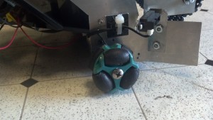
omni wheels with black gritty rubber

3 omnis, each with 6 black roller wheels make EARL a true 18-wheeler.

From the start, we decided to drop omni wheels onto our robot. Besides looking cool, we liked them because they gave us the ability to strafe along a wall. This would allow us to play defensively, riding alongside the yellow scoring wall to block our opponents. However, we ran out of time to implement this behavior, and gameplay didn’t end up being fast enough at the end game to necessitate this tactic.

Originally, our the rollers on our omnis were a smooth surface, but this proved to be too little friction to drive effectively. Consequently, we coated the rollers in a mix of rubber paint and sand, which significantly increased our traction.

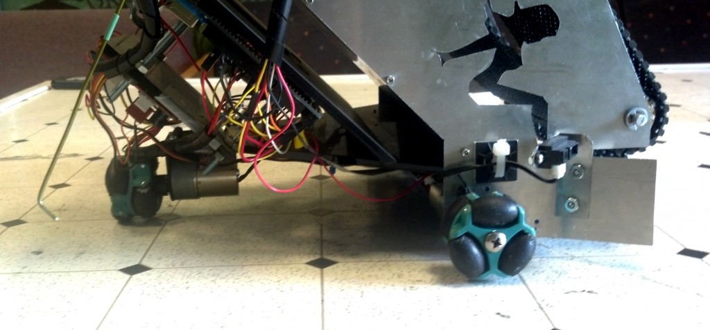
Trucker ladies in the front, omnis on the bottom, and the end of a whisker switch are visible in this side view of the robot.

Trucker ladies in the front, omnis on the bottom, and the end of a whisker switch are visible in this side view of the robot.

As a programmer, I also think omnis are fun to program for because they allow for holonomic drive, which I played around with back in FIRST Robotics. The freedom to locomote in any direction in the plane is really convenient. You wanna get somewhere specific? You just do it. For example, my high school team and I made this cute robot  that uses a holonomic drive system to align with a feature on a playing field wall.

Lights

The headlights are visible in the top of the robot. Photo c/o Fred M.

The headlights are visible in the top of the robot. Photo c/o Fred M.

Mounted atop the metal frame, the headlights are a distinguishing feature of our robot. We put them on in the hopes that they would illuminate the field, creating a more even image for processing, but they ended up creating a confusing gradient, so we powered the lgihts off during matches. On the plus side, they contributed significantly to our trucker theme!

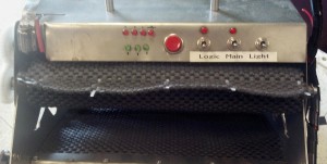
On the other side of the robot is a dashboard with switches and LEDs. The switches power on the robot’s logic, main power, and lights, and some of the LEDs show the state of the power systems and batteries. The remaining LEDs indicate the charge on our robot’s onboard flux capacitor, which was tricky to measure, but we were able to do after importing the python module random.

LEDs and switches are mounted on the dashboard  on the back of the top of the robot, above the hopper where balls accumulate after being pulled up by the tread.

LEDs and switches are mounted on the dashboard on the back of the top of the robot, above the hopper where balls accumulate after being pulled up by the tread.

Ball Intake Sensor

Mounted underneath the mesh of the ball intake ramp is a sensor for counting how many balls we pick up from the field, which is useful to know if we don’t want our robot wasting time trying to score until some threshold number of balls is collected. Instead of using a breakbeam or similar single Boolean sensor, we implemented an array of sensors, so we could have an accurate count even if we picked up multiple balls at the same time. Each element of the array is a limit switch read independently by the computer. Because switches are bouncy and noisy, the code lowpasses the signal from each sensor. In addition, the code compensates for one ball tripping two neighboring sensors by interpreting adjacent detections as a single ball detection.

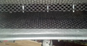
Pictured is the mouth of the tread conveyor; beneath the mesh on the bottom is a line of limit switches, contributing to a slight bulge in the material.

Pictured is the mouth of the tread conveyor; beneath the mesh on the bottom is a line of limit switches, contributing to a slight bulge in the material.

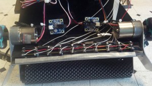
Wiring connects each limit switch on the underside of the ball detector array.

Wiring connects each limit switch on the underside of the ball detector array.

Other Notes

One neat aspect of the MASLab robots was how we set up the processing. The code for our robot ran on an Acer Aspire One laptop, which talked with an Arduino Mega over serial for sensor input. This was a pretty convenient system because it’s easy to implement code on the laptop, and we could implement processor-intensive things like processing the images from our webcam on our laptop.

In the end, we won 3rd place as well as the Two Sigma design award. Thanks Two Sigma!

You can check out the full competition videos on the MASLab 2013 YouTube Playlist, but I’ve pointed out good clips of our robot below with links to relevant starting points in the videos.

You can read more about MASLab at the competition site including how to register. You can also read our team journal for the lulz.

My hall has some attiny13a chips lying around, so I decided to give it a go programming them last night. Here’s my adventure of learning how to program a AVR.

I didn’t have a serial cable or a programmer, but I heard you could program these with an arduino as an ISP, and I had one of those. I turned an arduino nano into a programmer using a tutorial provided by the High-Low Tech Group at MIT.

One thing to note about the tutorial is that you should upload the program that runs the arduino as an ISP before wiring up the pins of the arduino per the tutorial’s diagram. Specifically, the wiring calls for a capacitor to disable the reset switch of the ‘duino. If you drop this cap in before uploading the ISP program, your computer won’t be able to reset the ‘duino to run the bootloader to upload the program. Rather, the capacitor is useful after uploading the ISP program. After the ‘duino ISP is running, the cap keeps the ‘duino from being reset by the computer, so the ‘duino can instead reset the AVR. I was confused by this, and it wasn’t immediately obvious what was going on without considering the ‘duino is reset before uploading programs to it.

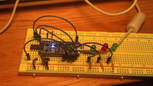
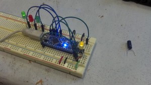
This arduino nano is wired up as an ISP for the attiny (left). I also included debug LEDs that represent communication, error, and status respectively.

This arduino nano is wired up as an ISP for the attiny (left). I also included debug LEDs that represent communication, error, and status respectively.

Next, I also wanted to use the arduino IDE also to program the tiny. To do this, I followed instructions provided by another hacker which draw on instructions from the same group at MIT but update them for compatibility with the attiny13a. Here’s the result.

I used this 'duino as an ISP to upload a program to the attiny13a on the right. The program makes the tiny blink the yellow LED on and off.

I used this ‘duino as an ISP to upload a program to the attiny13a on the right. The program makes the tiny blink the yellow LED on and off. I removed the cap (right) per the note earlier.

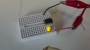
Detached from the arduino, the tiny still runs the program to blink a yellow LED on and off.

Detached from the arduino, the tiny still runs the program to blink a yellow LED on and off.

These are pretty cute.

It’s freezing outside. Literally, there’s literally a blizzard, and Boston is shut down. Appropriately, I made a thermometer last week.

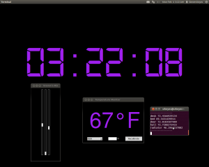
Screenshot from 2013-02-04 03_22_08-cropped

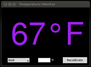
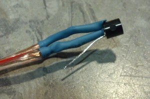
67°F in a blizzard? Actually, it’s a thermometer for my room. It consists of an array of LM335Z temperature sensors that I’ve distributed around my room. Each sensor has wires leading back to my Arduino, and the Arduino is connected to a USB port on my desktop.

The third pin of the LM335z is for calibration pin, but I'm doing calibration in software.

The third pin of the LM335Z is for calibration, but I’m instead doing calibration in software.

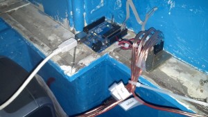
Wires come from sensors to a perfboard to the arduino, which sits atop the molding in my room.

Wires come from sensors to a perfboard to the ‘duino, which sits atop the molding in my room.

I used Python to talk to the Arduino over serial. Then, I created a module for reading the temperature from a sensor on a pin on the ‘duino. I created a temperature object for storing temperature values in a way easy to convert between absolute temperature in Kelvin and temperature in degrees Fahrenheit as well as other representations.

In the sensor-reading module, I also included a method for calibrating each sensor with a list of known values. Then, when the sensor is called to give a reading, the method makes a linear regression of the calibration values and uses the regression to correct the new reading. I used the numPy module to implement a least squares linear regression. I also used the pickle module to serialize these calibration points and save them to a backup to avoid re-calibrating between program restarts.

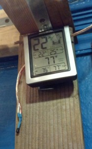
It doesn't feel like 77 in here...

It doesn’t feel like 77 in here…

To gather calibration points, I’ve been leaving a digital thermometer by each sensor and regularly submitting readings from that thermometer to my program using the user inputs at the bottom of the screenshot at the top of the post. In the window, the first input is a menu to select a sensor by location; the second is a box to type in the true temperature; and the third is a button that takes the true temperature along with the current reading from the selected sensor and saves them to the list of calibration points for that sensor.

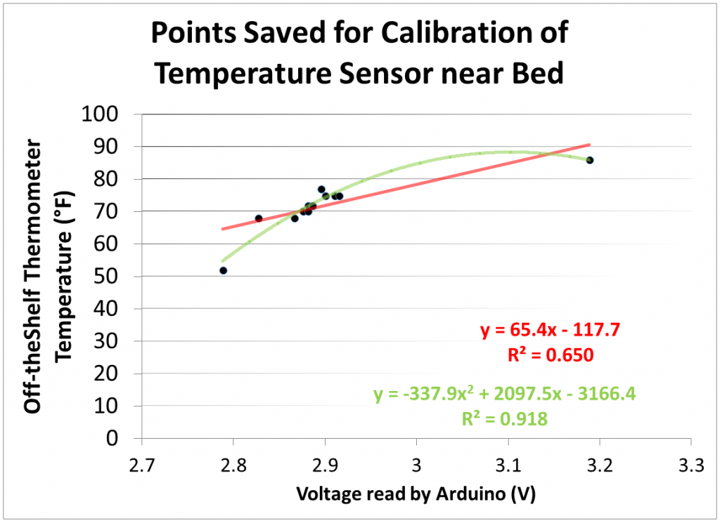
I’m concerned that my off-the-shelf digital thermometer is not very accurate, so I’m going to borrow a better thermometer soon, but I also hope to remove some precision error by data averaging. Also, I suspect a linear regression may not be ideal for calibration–as you can seem below, a quadratic regression fits much better, for example.

Graph of calibration data

Several calibration data points for a sensor produced this graph, overlaid with a linear regression (red) and a quadratic regression (green).

At the top level, I’m averaging the readings from all the sensors and displaying them in a UI that I made with the tkinter module. I mentioned the calibration button earlier; the large number above it is the average temperature from the sensor. For now, I’m also printing the reading off every sensor to a terminal. In the future, I plan to display a weighted average of the temperature based on places I’m likely to be–weighting my desk and bed heavily, for example. Better yet, weight the reading dynamically based on where I currently am in my room or where I am likely to be in the near future. I also plan to add more sensors.

The radiator temperature seems incredibly low for a radiator because my radiator was turned off and is adjacent to the window, which is very cold.

The radiator temperature seems incredibly low for a radiator because my radiator was turned off and is adjacent to the window, which is very cold.

One thing that surprises me is how fast these sensors respond to changes in temperature. The temperature read off one instantly changes a few degrees upon touching it with a finger. Yet, when untouched, they don’t vary by more than half a degree for several minutes.

Next, I want to make a controller for my radiator and add it to the system. I’ll also update you on the MASLab robot I worked on last month. Also, I started using github, which is nice.

I’ve been learning to spin Poi with the MIT Spinning Arts Club since freshman year. Poi are tethered weights that a performer spins to create cool effects and illusions.

A variety of props can be used at the ends of poi leashes. One interesting prop I’ve found is an array of LEDs. By alternating which LEDs are active, the performer can create cool patterns. This is sometimes called pixel poi or LED poi, and you can see very nice commercial ones available here, here, here, and here. Along similar lines, here‘s a hacker who attached a persistence of vision display to a string to create a pixel poi effect.

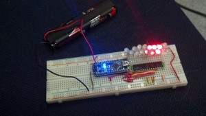
Images on the above sites have long-exposure pictures of the products to show their patterns traced out over big arcs. However, the effect shouldn’t be confused with the persistence of vision (POV) effect and POV displays, which would require spinning poi at more than 25Hz, which is about an order of magnitude faster than I can spin poi. I decided building some of these would be a good exercise to gain experience building cool things with circuits, and I also had some ideas for improvements. So far, I’ve created a small array of LEDs that I control with an arduino, and I’m working on finishing a poi. For the physical construction of the pixel poi, I plan to use about 15″ of 3/4″ polycarbonate tubing per poi. My plan is to house the LEDs and some circuitry inside while wires run up a short leash to the grip. Inside the tube will be a slack column of wires, LEDs, and circuitry tied to a pretensioned piece of cord to prevent loading the leads of the components. Above the grip, I’ll have a microcontroller and battery attached to each wrist. Long term, I plan to house all the electronics in the poi themselves, but this is more convenient now. As for the circuitry, I acquired two arduino minis, one for each poi. I also have a bag of RGB LEDs, and I plan to use 16 pixels per poi, where each pixel is probably 1 LED. To control the LEDs, I’m using some PWM drivers ICs, specifically the 16-channel TLC5940, which I hear is popular for this purpose. To control 16 RGB pixels, I’m using 3 chips. For now, I’m using some AA batteries to power the system. Before I started assembling the poi, I created a scaled-down circuit of one arduino and one 5940 driving 16 RGB LEDs on only one channel. I used the tlc5940arduino library, and I could drive the LEDs with various patterns. Shown below is a picture of a Knight Rider pattern in which a dot travels up and down the row of LEDs. The dot spans a couple LEDs, and, based on its direction of travel, it’s brightest at the front and dimmest at the rear, demonstrating how driving LEDs by PWM can produce a range of intensities.

Here I'm just using one 5940 to drive only the red channels of 16 RGB LEDs

Here I’m just using one 5940 to drive only the red channels of 16 RGB LEDs.

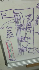
I also created a checkerboard pattern on the LEDs. The pattern alternated faster than 25Hz, so it appeared like unblinking LEDs when the breadboard was static, but waving the breadboard around revealed blinking LEDs. Next, my plan is to add more 5940s as well as lengths of wire in place of the breadboard to create the full poi. A whiteboard diagram shows 7 wires that travel down the tube. 5 are signals for the 5940, and 2 are power. The LEDs are placed between the output channels of the 5940 and ground.

2012-09-27_00-35-44_71-resized

In purple, this diagram shows wires between the microcontroller (µC), the 5940 PWM drivers (PWM), and the LEDs. Bottom left in red and green is a sketch showing the drivers and LEDs spaced evenly along a column, drawn to estimate how much wire I needed.

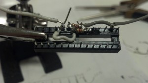
However, this plan requires soldering every LED pin and every 5940 pin, which is time-consuming. Shown below is a 28 pin socket, which I’m soldering in before inserting my actually 5940. At this point, I’ve soldered the input signal wires for about 3 sockets, but I haven’t yet started on the LEDs or the 16 output channel wires on the sockets, and I’m considering using instead a preassembled strip of LEDs for to expedite this.

2012-10-04_06-22-00_903-resized

Some pins here have resistors connecting them to generate proper voltages to control the chip.

I’ll keep you updated on my progress. Beyond a cool prop, I’d also like to use onboard sensors to gather data about speed, acceleration, and relative motion between the poi. Then I could use the sensors to control the patterns themselves or to create a musical instrument controller.

Last IAP, I ran into a problem. I have lots of kinds of audio signal sources: my laptop, my desktop, and mp3 players are the major ones, and each produces a separate mix of sounds. However, my preferred destination for all these sources is my pumpin’ Klipsh desktop speakers. I wanted a way to mix all these sources through software without having to acquire or build a lot of new hardware.

My solution was to use the sound card of my desktop, which has ports for line out, mic in, and line in. My speakers are connected to the line out port, and I have a 10′ trs cable running from the line in to my desk, which I generally have plugged into my laptop. I could hypothetically use the mic in to mix another device.

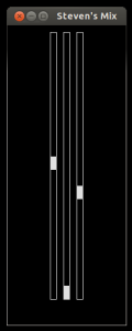
To control the relative mix of these signals, I programmed the mixer below in python 3. The first fader controls the master mix; the second fader controls the audio signal from only programs on my desktop computer; and the third fader controls the signal on the line in.

To make the faders, I used the tkinter module and created a Fader class, which inherits from tkinter’s Scale widget. The constructor for this class creates a Scale with the minimalist design shown, and it also gives Fader objects control over a Mixer object, which is described below. The Fader class also adds a changeVolume method, which is called when the user moves the fader on screen. The changeVolume method sets the volume of the Mixer object attribute based on the height of the fader.

screenshot-cropped-edit

The Mixer object comes from the alsaaudio module, which can be found here. From the site, “This package contains wrappers for accessing the ALSA API from Python.” A Mixer object represents a way to manipulate controls for different ALSA lines where each line carries a different signal. The names that ALSA gives to the lines that I’m controlling are “Master” for the master mix, “PCM” for the mix coming out of software on my pc, and “Line” for the mix coming into the line in port.

The changeVolume method also does some math before adjusting the mixer. The position of the fader on screen maps linearly to a height value read by the Fader object. However, the perceived intensity level of sound is logarithmic with respect to its amplitude. To compensate for this, the changeVolume method curves the input from the fader before it applies it to the mixer. As a result, moving the fader at low volumes causes the mixer volume to change slightly, and moving the fader at high volumes causes the mixer volume to change dramatically, so the intensity out of the speakers sounds linearly increasing from bottom to top of the fader.

This mixer is pretty minimalist, but in the future it would be cool to have something more like the native mixer in Windows 7, which not only shows the fader but also bars visualizing the volume of the signal for each input.

Now, I’m working with some temperature sensors to regulate things in my room and display information about temperature on my screen, too. I’ll keep you updated!

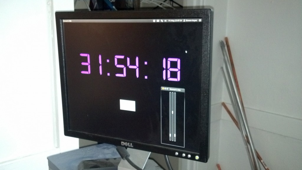
If you walk into my room, you might see an interesting interface on my desktop:
2012-05-25_07-54-35_738-resized

I’m referencing the clock and the mixer, not Unity :p

These are two tools I made freshman year: a unique clock and an audio mixer. They run on my desktop, an old HP computer that I got off reuse. I made the clock first, so I’ll describe it first and save the mixer for a later post.

Background

Laypeople count “1, 2, 3, …”; programmers count “0, 1, 2, 3, …”. However timekeepers must be really terrible at counting because, for each am or pm period, they count “12, 1, 2, 3, …”! A couple standards for time exist around MIT, whose students often require timekeeping that is unambiguous even during the night hours.

Take for example Random Standard Time (RST), created to accommodate the waking hours of residents of Random Hall. In RST, each day starts at 6:00 and ends at 30:00. 6:00 RST aligns with 6:00am of that day while 30:00 is actually 6:00am the next morning. This way, residents can avoid the inconvenience of day changes at midnight.

Another example is the practice of adding a delay to events around midnight to avoid the confusion of day changes. Suppose, for example, I have a pset due 9am Wednesday. If I want to tool with my friends 7 hours before the pset is due, it is ambiguous what day to tell my friends to join me. To employ the delay strategy, I would say to meet 11:59 Tuesday night, which falls unambiguously under a certain 24 hour period. Then, I would add that we should be 2 hours late, thus meeting at the desired time. One alternative phrasing, meeting at “2AM Tuesday night”, sounds a lot like meeting at “2AM Tuesday”, which would allow far too little punting!

Because hackers are notoriously late, a 15 minute delay is sometimes called “Hacker Standard Time”, so the phrase “HST” can be implemented when using the delay strategy described above to concisely remove ambiguity for events around midnight.

Beyond these standards, there’s lots of cool ways to count time. One more practice listed in the Wikipedia article is to continue counting past 23:59 to express nighttime am hours as 24:00, 25:00, 26:00, etc, and this is the basis for my clock.

Besides timekeeping, RST also implies a system of datekeeping in which every day is still 24 hours but each day is shifted. However, the following rule is my favorite system for datekeeping: it is considered a new day if at least two of the following happen; otherwise, it’s still night of the previous day.

  • You eat breakfast.
  • The sun rises.
  • You wake up.

This system is great because, even if you pull an all-nighter, you are still guaranteed a new day as long as you eat something that you consider breakfast, and there is a new sun in the sky. Conversely, maybe you slept all afternoon, woke up at 11:00pm, and you’d like it to be tomorrow already so you can start feeling productive. Simply chug some cereal and you’re golden.

Implementation

Regardless of how you keep dates or time, I wanted to have some fun making a unique clock for my room, and I wanted to practice some of the Python I had been learning in classes like IAP’s 6.S189, so I made this clock. I used the tkinter and time modules for the first time. I also tried Python 3 instead of Python 2, which we used in class. The font is Digital-7, which is free for personal use. I made the font large enough that I could read it from bed without glasses, which is more than I can say for my cell phone or alarm clock.
screenshot3-edit

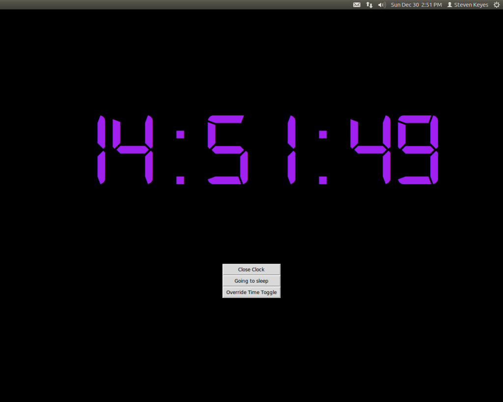
Example shot at 2:51pm

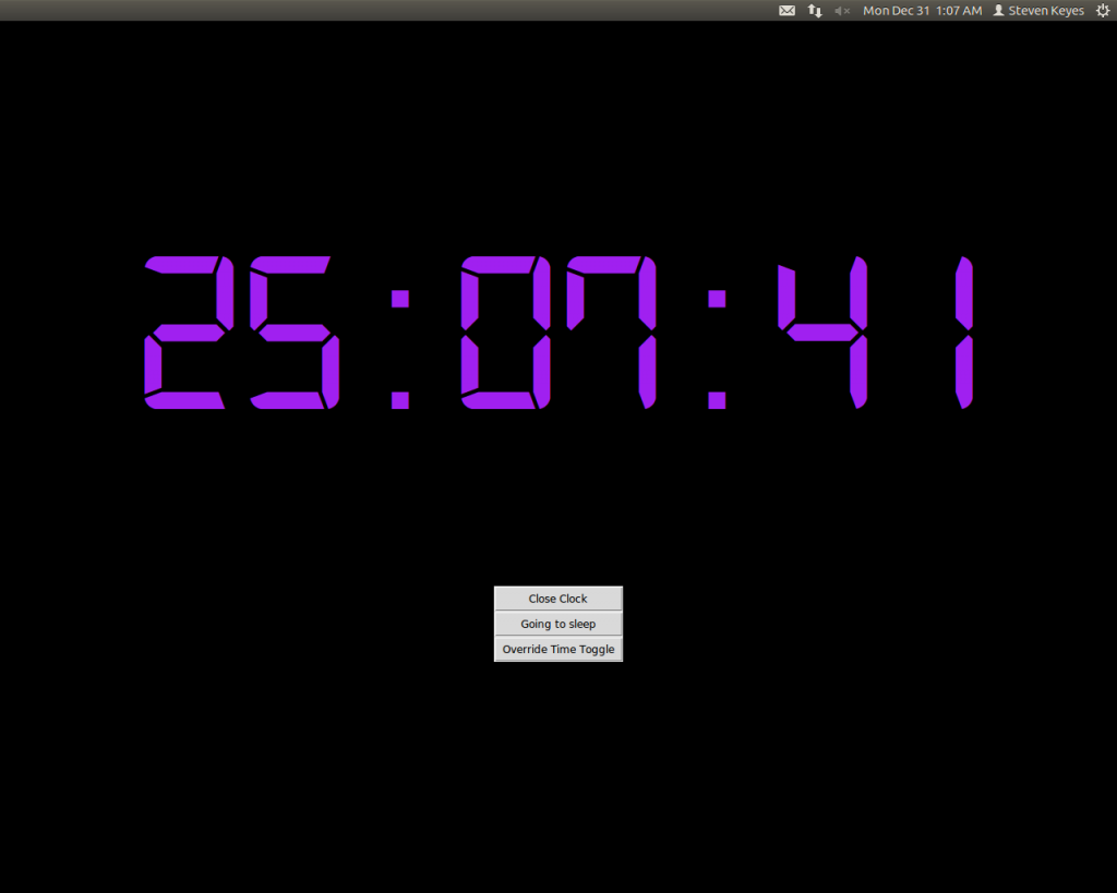
For my clock, the time starts synced with normal time when I wake up. Rather than am or pm, the clock runs from 0:00 to 23:59. Then, at midnight, it keeps counting up through 24:00, 25:00, etc until I press a button to tell it that I’m going to sleep. When I wake up, I press a button to tell it, and the clock re-syncs with standard time.
screenshot4

Example shot late in the night of 30 December; you can see in the top left that it’s actually 1:07am on 31 December

To do this, the program toggles a Boolean at midnight to indicate that the time is extended from the previous day. The “Going to sleep” button seen above disables this toggle, so the clock rolls over to 0:00 at midnight. A “Waking up” button, which appears in place of the “Going to sleep button” re-enables the toggle for the next night. The “Override” button seen above manually toggles the variable, and the “Close Clock” button closes the clock.
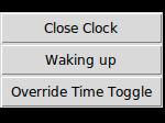
The "going to sleep" changes to a "waking up" button after being pressed

The “going to sleep” changes to a “waking up” button after being pressed

For my curiosity, I’d also like to implement a program that keeps a log of when I sleep. However, the interface for this would probably be more convenient on a phone or some device that I carry with me regardless of where I sleep, so a program on my desktop is not convenient. I plan to link this my clock to reset it remotely.

P.S. even if you’re away from your dorm room for winter break, you can still apparently ssh into your desktop and take screenshots: xwd -out screenshot.xwd -root -display :0.0